Available
TELTONIKA TELEMATICS
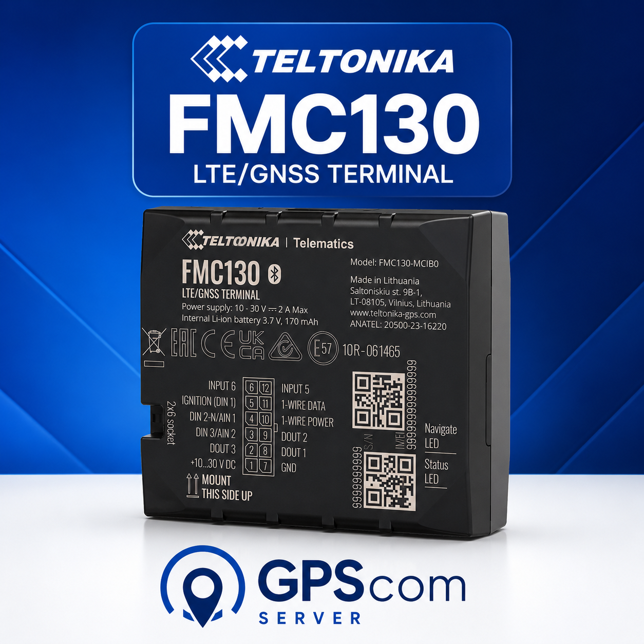
FMC130
Detailed connection diagram for the Teltonika FMC130, covering power supply, ignition, digital and analogue inputs, digital outputs, 1-Wire and LV-CAN.
10–30V DC 3× DIN 2× AIN 3× DOUT 1-Wire LV-CAN

Your wishlist is empty
Your comparison list is empty
Your cart is empty
A technical library of detailed GPS tracker wiring and connection diagrams. Choose your device model to see its pinout, power supply, inputs and outputs, and useful installation notes.
Tap a device to open its detailed wiring guide and connection diagram.
Detailed connection diagram for the Teltonika FMC130, covering power supply, ignition, digital and analogue inputs, digital outputs, 1-Wire and LV-CAN.
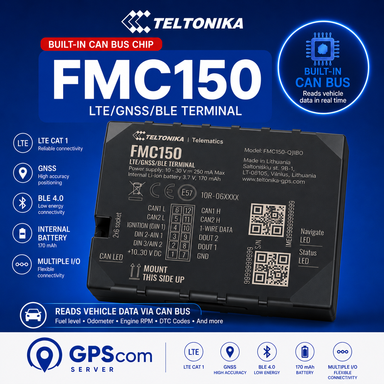
Detailed connection diagram for the Teltonika FMC150 with its integrated CAN adapter, two CAN lines, digital and analogue inputs, digital outputs and 1-Wire.
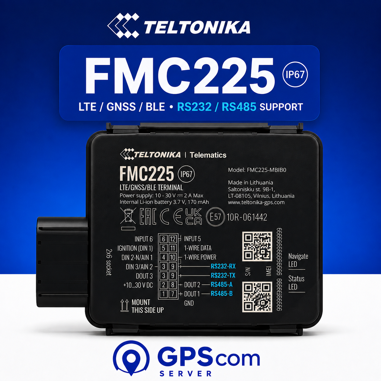
Detailed pinout and connection guide for the IP67 Teltonika FMC225, covering power supply, ignition, RS232, RS485, 1-Wire, DOUT1 and LV-CAN.
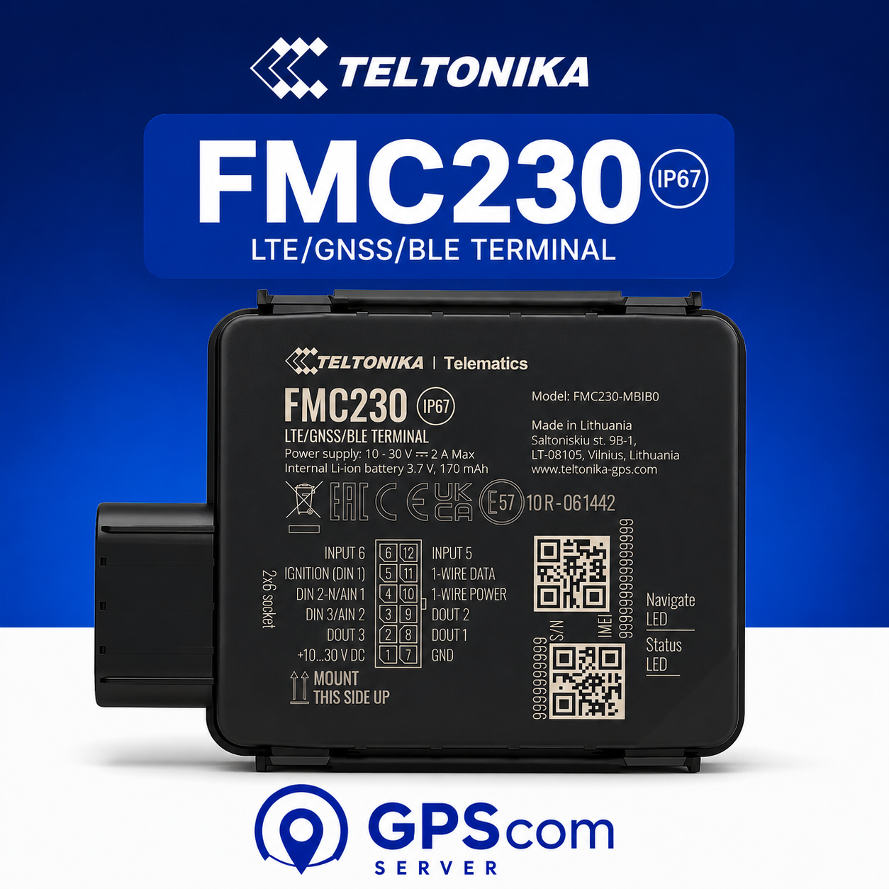
Detailed connection diagram for the waterproof IP67 Teltonika FMC230, covering power supply, ignition, digital and analogue inputs, digital outputs, 1-Wire and LV-CAN.
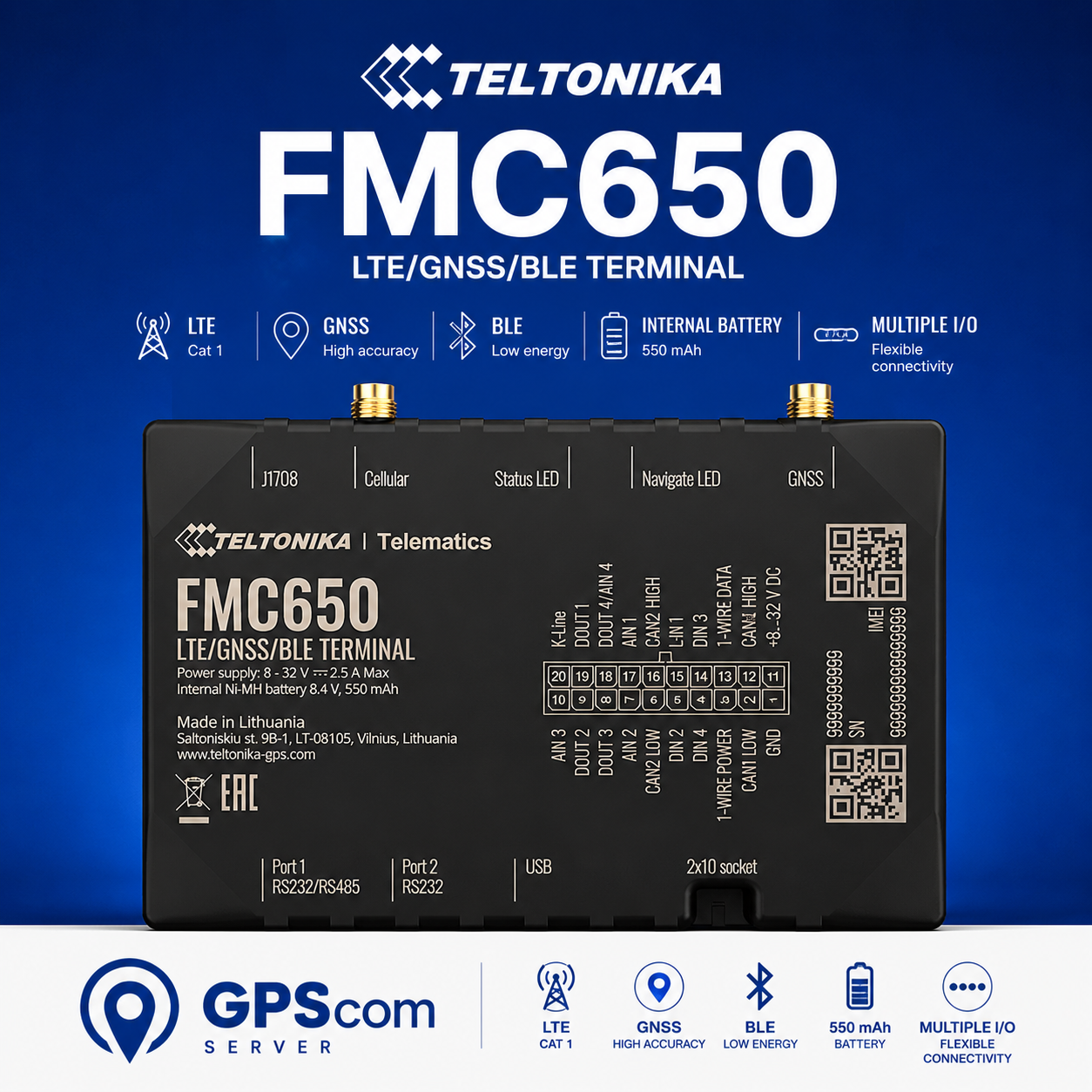
Detailed connection diagram for the professional Teltonika FMC650, with 8–32V supply, four digital inputs, analogue inputs, digital outputs, dual CAN, 1-Wire and K-Line.

Detailed wiring diagram for the Teltonika FMC920, covering power supply, ignition, DIN1, AIN1 and DOUT1.

Detailed wiring guide for the IP69K Teltonika FTC961, with a 10–90V DC high-voltage supply, ignition on DIN1, analogue input AIN1 and digital output DOUT1.
These guides exist to give quick access to the connection points that matter on a GPS tracker. For each model you can see the wiring diagram, what each wire does, and the basic electrical connections.
This section is updated continuously with new models, wiring diagrams and technical installation guides for GPS trackers.

© 2001-2026 GPScom Technologies · Commercial Reg. (GEMI) No. 180170606000